-40%
2KW Stainless Steel OCF Dipole with vertical radiator--80-6 Meters
$ 163.65
- Description
- Size Guide
Description
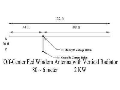
Quality ham radio antennas built to last a lifetimeB-Square Engineering is proud to introduce a premium quality multi-band HF antenna capable of meeting the most extreme demands of endurance, performance and power capacity. This antenna is based on the latest design enhancements of the Carolina Windom which is rapidly becoming the workhorse wire antenna of DXpeditions around the world and for good reason. This antenna is designed to be used at heights of only 25 to 45 feet. It utilizes a twenty foot long vertical radiator which serves to fill nulls and provides unbelievably low take off angles. Based strictly on the familiar numbers, published from several sources, our 80~6 meter antenna starts with a 132 foot long off center feed dipole, fed 33% from the end. It uses a 4:1 Ruthroff voltage balun to feed the dipole. Feeding the balun is a twenty foot long section of 50 ohm coax which is also used as a vertical radiator. This is accomplished by the use of the voltage balun, just mentioned, which allows RF current to flow on the outside of the coax shield. To prevent the RF from continuing on into the shack, a 1:1 Guanella current balun is placed at the end of the twenty foot radiator, opposite the dipole.
The design is brilliant and simple, however we have never seen an execution of this antenna that meets our standards for quality, endurance and power capacity. That’s where we have raised the bar. If you have had failures with this type of antenna or know of those who have, you are sure to appreciate our execution of this fine design. This antenna uses only the finest materials and craftsmanship to provide the ultimate in long lasting value.
STAINLESS STEEL CABLE:
At B-Square Engineering we are obsessed with the advantages of stainless steel. We’ve been building wire antennas with stainless steel cable for years. It was only natural to utilize it in this antenna. Our 80~6 Meter model, as shipped, is 132 feet long. However, by using stainless cable clamps, at each end, we provide an extra 4 feet of cable on the short leg and 8 feet of cable at the long leg which can be used to lengthen the antenna more than eleven feet, if needed or desired. By loosening the clamps and adjusting the length of the cable that folds back onto itself the length of the antenna can be adjusted without cutting or splicing!
RUTHROFF 4:1 VOLTAGE BALUN:
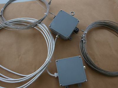
We tested countless voltage baluns, purchased several and wound even more. After months of testing, we developed our own balun that is wound using high voltage wire over two massive toroids. The resulting balun provides excellent performance from 1.5 MHz to over 70 MHz with a power capacity of over 2KW! The balun is housed in a commercial junction box. The ends of each of the stainless steel dipole legs are routed into the box and soldered directly to the leads of the balun.
GUANELLA 1:1 CURRENT BALUN AND VERTICAL RADIATOR:
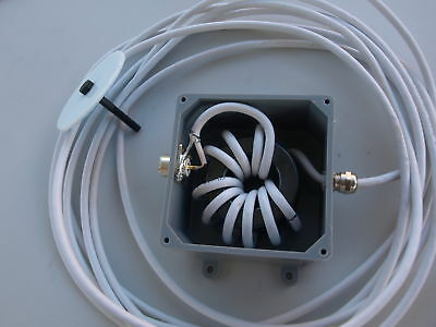
The 1:1 current balun and its attachment tend to be a weak spot in all the other offerings of this antenna we’ve examined. Since this balun (or choke) is used to make the current running on the outside of the coax shield “think” it has come to the end of the conductor, voltages can get quite high. This is not a good place for a mechanical connector, particularly a cheap PL259 crimped onto a piece of RG58 as is commonly being done. These connectors commonly fail due to arcing at high power levels. To eliminate the common problems of failure seen at this connection, we opted to eliminate the connector altogether. We fabricate our vertical radiator using LMR240 or equivalent coax. It is soldered directly to the leads of the 4:1 balun, at the top, and passes out of the enclosure through a watertight feed-through. It then extends downward for twenty feet (on the 80~6 meter model) where it enters the enclosure for the 1:1 current balun through another watertight feed-through. Inside this enclosure, the coax is wrapped onto two large toroids where the end (where the voltage levels are more modest) is soldered to a silver plated SO239 connector.
ELIMINATION OF MECHANICAL CONNECTIONS:
As you might have guessed, another item we obsess over is the elimination of mechanical connections. In our execution of this antenna, we solder: the dipole elements to the 4:1 balun, the 4:1 balun to the vertical radiator, the coax for the vertical radiator is passed through the toroids forming the 1:1 balun and is soldered to the SO239. By doing this, the only mechanical connection in the entire antenna system is where the user attaches his feed-line.
PREASSEMBLED AND READY TO INSTALL:
We assemble all the components and provide a package that is ready to install. You’ll have to find a spot to sting it up.
WHAT TO EXPECT ONCE THE ANTENNA IS INSTALLED:
Although this is a viable multiple band antenna, we recommend using a tuner to get the most out of it. We have found that by using a tuner, all bands (including WARC) from 160 meters to 6 meters can easily be worked if both of the horizontal elements are hung at heights between 25 and 45 feet, without any adjustments to the antenna length. If time is invested in adjusting the antenna length, it is likely that the vswr for several bands (80, 40, 20, 10 and 6M) can be brought to below 1.5:1, if the antenna is at a relatively high height (35 feet or more). However this gets trickier at lower installation heights. Such is the nature of any OCF dipole. At lower installations (particularly below 25 feet), it might be possible to adjust to a low vswr for the low bands (80 and 40) only to see high readings on the high bands (20 and 10). At low installation heights, it’s generally easier to adjust the length to yield good vswr readings on the higher bands (6, 10, 20 and possibly even 40). At heights above 45 feet, the antenna behaves best on the lower bands. Again this is the nature of any OCF dipole. In such cases the impedance of the feed point increases above what a 4:1 balun can effectively match. As just mentioned, we recommend the use of a tuner. It can eliminate a lot of headaches as well as compensate for countless variations in different installations.
With all that said, this is an antenna made to be strung up, loaded up and let it amaze you. Use it at the home QTH hanging from sixty foot towers, at field day strung ten feet off the ground or on a DXpedition attached to palm trees. Being constructed as well as it is it can be put up and left for years to come or dragged from cite to cite. It is built to take whatever gets thrown at it.
WHAT ABOUT RF GETTING BACK INTO THE SHACK?
Since this antenna design encourages current to flow down the outside of the coax shield, a robust current balun is required at the bottom of the vertical radiator. We build our antenna with the finest such current balun available, based on proven W2FMI techniques. Currents on the outside of the shield see extremely high resistances and are choked out ([email protected], [email protected], 9.5K@7MHz, 20K@14MHz, 38K@28MHz, and 68K@50). For most applications no problems are ever experienced. A reasonably good station ground will generally eliminate any effects of the worst case scenario (legal limit power levels on 1.8 MHz). Nonetheless, for anyone running an amplifier on 160 meters, we advise grounding the shield of the coax feed-line outside the shack.
HOW MUCH POWER WILL IT HANDLE?
This antenna is built to withstand continuous loading of 2 KW, regardless of mode. Both baluns have pairs of large, high quality toroids. By eliminating problematic mechanical connections, arced out balun connections are dealt with forever. If you run legal limit power, this antenna is made you.
WHAT IF I'M NOT SATISFIED WITH IT?
Like all of our products, we're sure you will be delighted with it. However, if for any reason you're not, return it for a full refund.
Price: 9.95
